RigExpert AA-230 ZOOM – How it works?
Structure diagram
The structure diagram of RigExpert AA-230 ZOOM is located below:
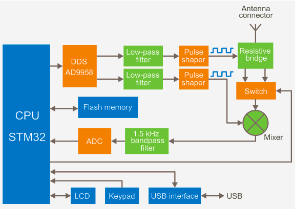
The “brain” of the analyzer is STM 32-bit RISC microcontroller. It controls a AD9958 DDS chip running at 500 MHz and generating two sinusoidal signals. Both signals are low-pass filtered and then put through pulse shapers, producing two square signals with LVDS levels. Resistive brigde was chosen to measure parameters of a load because of its simplicity and good frequency response. The switch commutates two outputs of the bridge. After the switch, the signal is mixed with the second channel output to produce audio frequency of 1.5 kHz.This signal is then filtered and fed through the 16-bit ADC to the microcontroller. The 290×220 color TFT display and the 6×3 keys keypad are connected directly to the CPU. The analyzer is equipped with 4 Mbytes of external Flash memory to store measurement results. The USB interface chip allows connecting the analyzer to the PC.
Close look at the bridge
This is a diagram of the resistive bridge and its connection to the mixer:
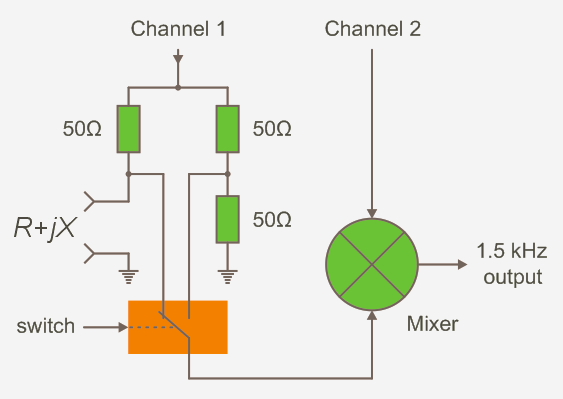
The switch which is controlled by the CPU feeds the signal from the certain side of the bridge to the mixer chip. When the load is totally active and its resistance is 50 Ω, the bridge is balanced and the switch outputs the same signal in both positions. This eliminates the need of calibration of the analyzer, also giving very good precision near SWR=1.