Every product our company manufactires is supplied with a standard USB cable . Additionally, we supply custom-made cables with various connectors for other RigExpert interfaces.
Unfortunately, at present not all USB cables are of good quality, so every cable we send to our customers should be carefully tested. Before bying a bunch of USB cables, we pick samples for testing according to basic requirements of the USB specification. First, availability and quality of the “shield” is checked. Then, resistance of signal and power wires is measured.
According to the specification, presence of four signal/power wires, inner shield and outer shield is required. In practice, some cables do not satisfy this simple requirement.
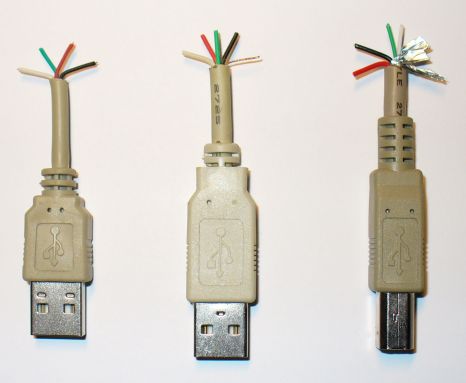
To meed the the specs, resistance of wires in a good USB cable should be measured as a fraction of an Ohm (for the standard length, 1.8 m or 6 ft). However, some cables show 2 to 5 Ohm, which is unacceptable for use with our products (at least, instability is guaranteed). We do not know what kind of material they are using to reach such a large resistance!
After the resistance is measured, several samples are connected to the PC and checked with our products.
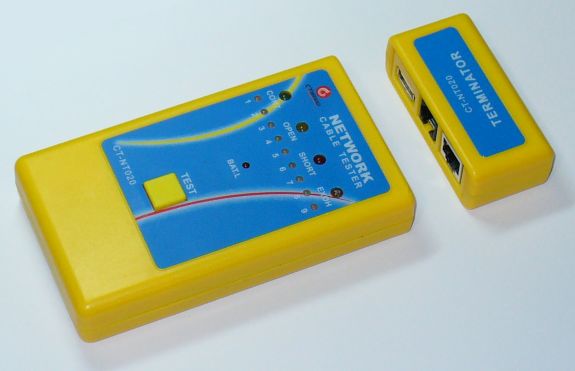
Even though the whole bunch of cables is accepted, every cable is electrically tested using the specialized cable tester, CT-NT020, made by CT Brand. The cable under test is connected to the tester as well as to the terminator. When the “TEST” button is pressed, the device checks integrity of all wires in the cable, as well as makes sure they are properly soldered to connectors.
As for transceiver cables for RigExpert interfaces, in addition to the incoming inspection of all wires and connectors, every cable is put under automated test before being shipped to the customer. This test is made by using a specially designed device so the human factor is eliminated and the quality is guaranteed.
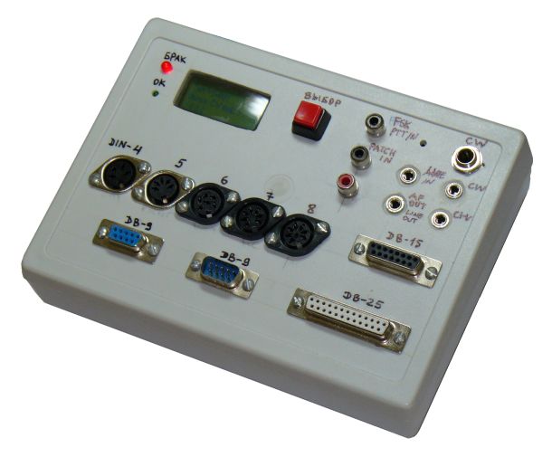
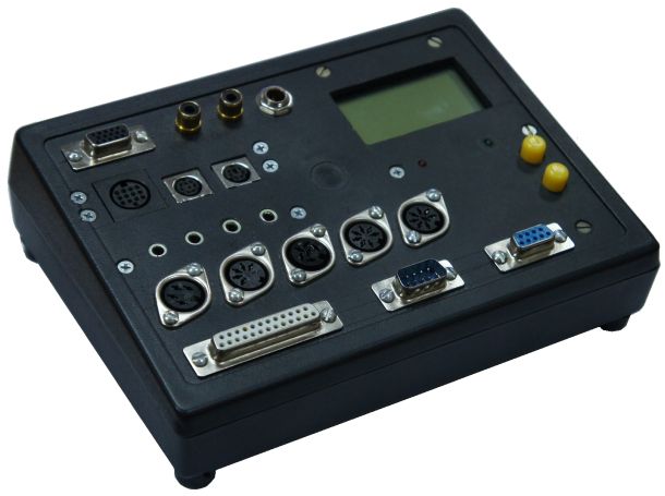
The top panel of the tester contains sockets to insert cables plugs into (some of sockets use external adapters). The type of cable to test is set by the “SELECT” button. Once the good cable is connected, the “OK” indicator is lit and the sound can be heard by the operator. In case of a faulty cable, the “DEFECT” LED turns on and the build-in LCD shows the cause of the problem. This device can detect shorts and open circuits, as well as wiring errors. Failty cables are returned to the factory to fix the problem.
The tester is built aroung the ATMEGA128 microcontroller. Every spare pin of the MCU is wired to the corresponding pin of the certain socket (excluding two pins used to connect the button, LEDs and the loudspeaker). The program scans the netlist and generates a pulse at the MCU’s output which corresponds to one of the pins of the current net. At the same time, all other microcontroller pins (which are set as inputs) are monitored. If the result corresponds to what is expected according to the netlist, the net is believed to be OK and the next net for the selected cable is checked. Otherwise the cable is considered defective and the display shows the cause of a problem (short or open circuit) and the location of a defect (for instance, open-circuit of pin 5 of the DIN-8 connector).
To add a new type of cable, extra connectors are added to the top panel (if needed). The netlist is modified and the new program is uploaded to the microcontroller.
Another tester has been built around three ATMEGA128 microcontrollers to extend I/O pins:
Denis Nechitailov, UR8US/UU9JDR
21-Nov-2014